| Since
all interactions of a solid body with a fluid, be it bird,
fish, aeroplane or ship, involve the flow of fluid over
a solid boundary, it can be said that Fluid
Dynamics IS the Science of the Coanda Effect.
The
Coanda Effect has come to mean attachment of a flow
to a surface beyond where we "expect" it to remain attached
- but this is a scientifically meaningless view.
The
classic example is that of fluid pouring out of a bottle
or teapot. If the fluid does not pour straight out but
flows around the lip, reversing direction before finally
succumbing to gravity and detaching, this effect of
"sticking to the surface" has come to be called the
"Coanda Effect".
A
more interesting example that anyone can perform for
themselves is to allow a fine continuous stream of water
to issue from the kitchen tap. Bring the rounded
pad of your first finger towards the stream until it
just touches. With the finger barely touching
the flow, the stream of water will be diverted around
the finger and spray out horizontally with some force.
The horizontal distance the water is projected is remarkable.
The best introductory article
available on the subject is still "Applications
of the Coanda Effect" by Imants Reba, which appeared
in the June 1966 edition of Scientific American.
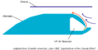 This
diagram shows a Coanda Thruster tested by Reba.
Air is ejected from a plenum at the front of the body.
A small step is inset into the surface of the body which
causes the ejected air jet to attach to the surface
and flow around it towards the upper surface.
A sheet of attached air called a Coanda Jet flows towards
the back of the thruster. This
diagram shows a Coanda Thruster tested by Reba.
Air is ejected from a plenum at the front of the body.
A small step is inset into the surface of the body which
causes the ejected air jet to attach to the surface
and flow around it towards the upper surface.
A sheet of attached air called a Coanda Jet flows towards
the back of the thruster.
In
so doing, it entrains by suction up to 20 times as much
air from the surrounding atmosphere as is in the jet
itself. A shroud placed around the body increases
the suction on the surrounding air even more.
Air
pressure on the front of the thruster is therefore reduced
by the entrainment suction so the body moves forward.
In addition, the afterbody made of flat angled segments
causes the attached Coanda jet or sheet to exert a positive
pressure on the rear of the thruster and so further
increase thrust.
We therefore have exactly the opposite situation to
a normal airfoil moving through air: instead of
positive air pressure on the front and negative pressure
on the rear, creating drag, we have Negative Drag - i.e.
Thrust.
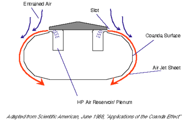 This
shows a model levitating device (hovercraft) tested
by Reba. The body of the device is made of short
flat surfaces, creating a so called Coanda Surface;
high pressure air ejected from an annular slot on the
top of the device flows around and down to wards the
bottom, entraining the surrounding air as it does so
and creating a partial vacuum on the upper surface -
a lower pressure region. Lift is therefore produced.
As with the thruster above, ambient air pressure is
increased below the device to increase lift. This
shows a model levitating device (hovercraft) tested
by Reba. The body of the device is made of short
flat surfaces, creating a so called Coanda Surface;
high pressure air ejected from an annular slot on the
top of the device flows around and down to wards the
bottom, entraining the surrounding air as it does so
and creating a partial vacuum on the upper surface -
a lower pressure region. Lift is therefore produced.
As with the thruster above, ambient air pressure is
increased below the device to increase lift.
Hydrofoil and Submarine Propulsion
Reba tested a model hydrofoil using a shrouded Coanda
thruster. The entrainment of the surrounding water
to produce thrust results in very little wake or noise.
Reba felt that a hydrofoil so equipped could reach speeds
of 80 knots. At about the same time in 1962, Stine
at the Huyck Corporation worked with Henri Coanda to
build a similar device using ejected steam for submarine
propulsion.
This concept has recently been re-invented by Australian
Alan Burns and developed by Pursuit Dynamics in the
UK. A 20 cm long "underwater jet engine" that
injects steam from an annular slot into an internal
Coanda nozzle is said to produce 30 HP output.
(See New Scientist, 1/3/03, P19).
Allied
Signal patented an internal Coanda nozzle using similar
principles in the late 90s. One application is
to eliminate the back pressure from the exhaust
of an internal combustion engine, but to instead suck
the combustion products out and so improve efficiency.
Circulation Control Wing
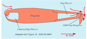 Circulation
Control Wing technology is one of the most important
potential applications of the Coanda Effect. Circulation
Control Wing technology is one of the most important
potential applications of the Coanda Effect.
The objective is to replace the lift devices on the
leading and trailing edges of a wing by use of Coanda
Surfaces and slot blowing instead.
The
diagram above is from AIAA 93-0644.
The first known use of this
"blown flaps" concept was on the prototype Boeing 707.
Boundary Layer blowing was successfully used on the
Hawker Siddeley Buccaneer to improve STOL performance
for aircraft carrier operations. The supersonic
TSR2 also incorporated blown flaps, allowing the 90,000lb
delta winged aircraft with a wingspan of only 37 feet
to achieve an approach speed of 130 knots: the
Concorde type droop nose was also eliminated since a
much flatter non alpha lift approach could be made.
In the late 1970s, Robert Englar tested a modified Grumman
A6 Intruder fitted with a prototype CCW system.
The aircraft was able to fly at less than 60 knots
and take off or land in less than 600 feet without catapult
or arrestor assistance.
Studies showed that a Boeing 737-100 weighing 105,000
lbs fitted with CCW and no headwind would take 3000
feet to clear a 50ft obstacle on take off (Sea Level,
ISA); the normal distance is 5000 feet. Landing
roll with no headwind would be 750 feet, compared
to 2000 feet for the conventional configuration.
A lightly loaded 737 (65,000 lbs) with a 20 knot headwind
would land in 300 feet with CCW lift devices.
CCW allows lift to be produced at Zero
Degrees Angle of Attack. Coefficient of
Lift (CL) of 8 at alpha = 0 was achieved
in tests.
CCW
has been criticised for requiring extra APU or engine
capacity to supply the bleed air to drive the slot blowing,
According
to Englar, a pressure differential of 13.8 psi at Sea
Level ISA is sufficient to produce a Coanda Jet
velocity equal to the speed of sound. Normal airfoils
achieve a CP of between -1.0 and -2.0; the
most efficient airfoil possible, the cylinder, has a
CP of -3.0. CCW equipped wings have
achieved CP of between -50 and -60, i.e.
the suction on the upper wing surface is 50 times the
freestream dynamic pressure.
Cross
feed can be used between the plena in each wing to maintain
flap blowing in case of an engine failure.
Engine
and APU manufacturers are studying a next generation
of APUs that would supply all the bleed air for pneumatic
systems, leaving the engines dedicated for thrust alone.
APU reliability will have to improve greatly before
this is achievable.
The X Wing
Helicopter
The
conventional helicopter is limited to a maximum forward
speed of about 200 knots; above that speed the decreasing
relative velocity of the leading edge of the retreating
blade with respect to the freestream air flow leads
to unsustainable loss of lift and lift asymmetry between
the forward going and retreating blades; if the helicopter
tried to fly even faster, the oncoming airstream would
impinge the trailing edge of the retreating blade causing
even more loss of lift.
Numerous designs have been put
forward since the 1950s for Compound Helicopters to
help solve this. The compound helicopter adds
a wing and thrust engines to transition to fixed wing
mode and unload the rotor at high speed.
Despite the great advantages
in efficiency, payload and range that this would bring,
no compound helicopter has been commercially developed.
Piasecki Aircraft have been trying to commercialise
this technology since 1955 and flew their first Vectored
Thrust Ducted Propellor (VTDP) designs in the 1960s:
in 2002 they were awarded a contract to convert an SH-60
to VTDP mode but this apparently was cancelled due to
disagreements over flight test rules.
Another solution is to use CCW
technology. In this application, the helicopter
rotor blades are constructed as Coanda surfaces.
A plenum and spanwise blowing slot run the length of
the trailing and leading edges, with a symmetrical cross
section to the rotor blade. Air is blown onto
the trailing edge of the forward going blades.
As the blades retreat, slot blowing is swapped onto
the leading edge of the blade, which is now a trailing
edge with respect to the forward motion of the helicopter.
This maintains lift on the retreating blades and theoretically
will allow forward flight speeds of 400 knots in pure
helicopter mode. Above that speed, fixed wing
mode is more efficient so the rotor is locked into place
to create an "X Wing". Differential slot blowing
is used in the transition phase to eliminate differential
lift as the rotor slows down.
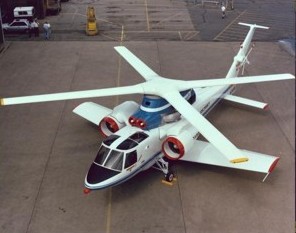 NASA
Ames developed a fully functioning flight test vehicle
in 1979 to test this X Wing concept (right): apparently
it never flew due to engine bearing problems.
It is more than just a compound helicopter with a wide
chord rotor: the circulation control rotor can
maintain helicopter mode lift at high forward speed
and use differential blowing for lateral control. NASA
Ames developed a fully functioning flight test vehicle
in 1979 to test this X Wing concept (right): apparently
it never flew due to engine bearing problems.
It is more than just a compound helicopter with a wide
chord rotor: the circulation control rotor can
maintain helicopter mode lift at high forward speed
and use differential blowing for lateral control.
US Patent 4,626,171 "Rotor Blade Construction for Circulation
Control Aircraft" was then issued to United Technologies
(Sikorsky) in 1986 for the same technology.
The latest embodiment of this
idea - the Canard Rotor Wing - is a stopped rotor design
that does not as far as we know use circulation control
or slot blowing to increase maximum forward speed in
helicopter mode, or to control the transition from helicopter
to stopped rotor mode.
A search through the patent
literature shows that quite a number of stopped rotor
X Wing configurations have been developed, such as
- US Patent 4,711,415 to Northrop
for "X Wing helicopter Scout Attack Configuration"
- US Patent 5,405,104 for "Stopped
Rotor Aircraft Utilising a Flipped Airfoil X Wing"
- US Patent 4,573,871 to the US
Army for "X Wing Aircraft Circulation Control"
- US Patent 3,794,273 to Teledyne
Ryan for "VTOL Rotor Wing Drone Aircraft".
VTOL
craft development has remained completely unchanged
since the 1930s with the exception of the NOTAR No Tail
Rotor technology by McDonnell Douglas Helicopters. This
technology eliminates the danger and noise of the tail
rotor and provides impressive performance improvements.
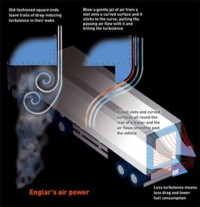
Drag
Reduction Spoilers for HGVs
A straightforward application of the Coanda Effect
has been the development by Robert Englar of spoilers
for Heavy Goods Vehicles. These could reduce fuel consumption
by up to 15% by reducing the negative pressure region
formed behind the trailer of a typical square edged
haulage vehicle.
Other Applications
Some
other applications and technologies that have been developed
using the Coanda Effect include:
- The
Gurney Flap
- Dual
Cavitating Hydrofoil Thrusters
- Drag
elimination and aerodynamic braking systems for automobiles
- The
NOTAR helicopter anti-torque system
- The
Flettner Rotor Wing
- The
Kline Fogleman Wing
- Wing in Ground Effect Vehicles
- The Carr Internal Wing (or Channel
Wing) Aircraft
References
Further Information
Further
information can be found in Meridian International's
1997 "Advanced Propulsion Systems Study". An updated
version will be coming out later in 2005.
|